- 您现在的位置:买卖IC网 > Sheet目录478 > MMA5248WR2 (Freescale Semiconductor)IC ACCELER 480G X-AXIS 16QFN
�� �
�
�6�
�SPI� Diagnostic� and� Programming� Mode�
�SPI� Diagnostic� and� Programming� Mode� allows� for� the� following� functions:�
�?� Programming� of� the� OTP� array�
�?� Reading� of� memory� registers�
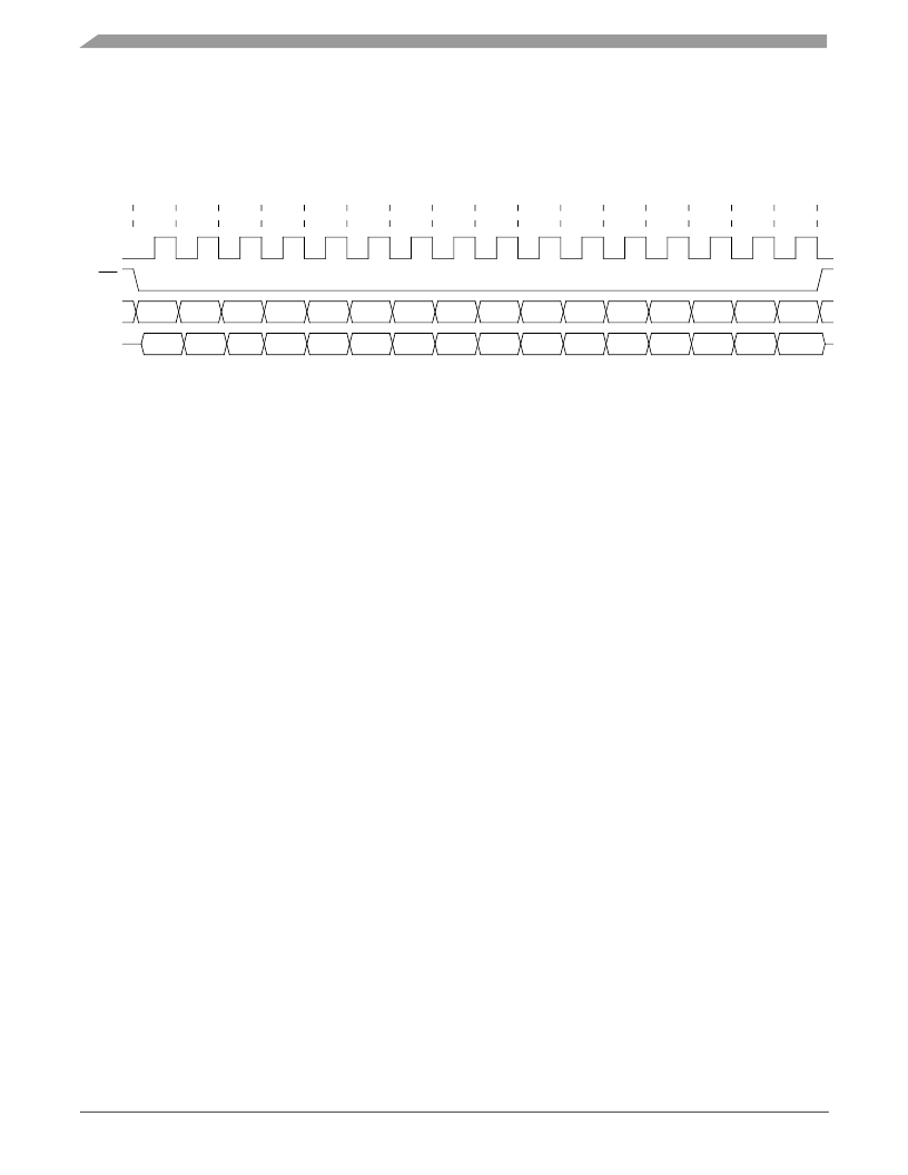
�SPI� transfers� follow� CPOL� =� 0,� CPHA� =� 0,� MSB� first� convention.� Figure� 7� shows� the� SPI� transfer� timing,� and� Figure� 45� shows�
�the� SPI� transfer� protocol.�
�BIT�
�15�
�14�
�13�
�12�
�11�
�10�
�9�
�8�
�7�
�6�
�5�
�4�
�3�
�2�
�1�
�0�
�SCLK�
�CS�
�D� IN�
�D� OUT�
�D15�
�D15�
�D14�
�D14�
�D13�
�D13�
�D12�
�D12�
�D11�
�D11�
�D10�
�D10�
�D9�
�D9�
�D8�
�D8�
�D7�
�D7�
�D6�
�D6�
�D5�
�D5�
�D4�
�D4�
�D3�
�D3�
�D2�
�D2�
�D1�
�D1�
�D0�
�D0�
�Figure� 45.� SPI� Transfer� Protocol�
�The� following� operations� are� supported� in� DPM:�
�?� Register� pointer� write�
�?� Register� pointer� read�
�?� Register� data� write�
�?� Register� data� read�
�?� Acceleration� data� read�
�6.1�
�6.1.1�
�Communication� Error� Detection�
�Data� Input� Parity� Detection�
�All� commands� except� for� the� DPM� Entry� command� employ� odd� parity� to� ensure� data� integrity.� For� Read� commands,� the� parity�
�bit� is� located� in� bit� D10,� and� the� parity� is� calculated� using� bits� D15� through� D11.� For� Write� commands,� the� parity� bit� is� located� in�
�bit� D9,� and� the� parity� is� calculated� using� bits� D15� through� D0.� If� a� parity� error� is� detected,� both� the� current� and� subsequent� com-�
�mands� are� ignored,� and� the� parity� fault� response� is� transmitted� during� the� subsequent� SPI� transfer.�
�6.1.2�
�Data� Output� Parity�
�All� responses� except� for� the� DPM� entry� response� employ� odd� parity� to� ensure� data� integrity.� Parity� is� calculated� using� the� entire�
�16-bit� message.�
�6.2�
�DPM� Entry�
�DPM� can� be� activated� at� any� time� during� the� operation� of� the� device,� provided� the� SPI� DPM� Entry� command� is� the� first� com-�
�mand� transmitted.� If� an� incorrect� DPM� Entry� command� is� received,� DPM� is� locked� out,� and� cannot� be� activated� until� the� device�
�is� reset.�
�The� device� responds� to� the� DPM� Entry� command� with� the� logical� complement� of� the� received� data� as� confirmation� that� it� has�
�been� received� correctly.� Upon� completion� of� a� successful� transfer� DPM� is� activated.� Once� activated,� the� device� will� remain� in�
�DPM� until� a� reset� condition� occurs.�
�Following� successful� transmission� of� the� DPM� Entry� command,� DPM� operations� may� be� completed� in� any� order.�
�MMA52xxKW�
�Sensors�
�54�
�Freescale� Semiconductor,� Inc.�
�发布紧急采购,3分钟左右您将得到回复。
相关PDF资料
MMA6331LT
SENSORS ACCELEROMETER 14LGA
MMA6341LT
IC ACCELER 3G/8G XY-AXIS 14LGA
MMA6361LT
IC ACCELER 1.5G XY-AXIS 14LGA
MMA6527KW
IC ACCELEROMETER XY AXIS 16QFN
MMA6556KW
IC ACCELEROMETER X AXIS 16QFN
MMA6826AKW
IC ACCELEROMETER XY AXIS 16QFN
MMA6854KW
IC ACCELEROMETER X AXIS 16QFN
MMA7331LR2
ACCELEROMETER 4G XYZ ENH 14-LGA
相关代理商/技术参数
MMA52XXAKW
制造商:FREESCALE 制造商全称:Freescale Semiconductor, Inc 功能描述:Xtrinsic MMA52xxAKW PSI5 Inertial Sensor
MMA52XXKW
制造商:FREESCALE 制造商全称:Freescale Semiconductor, Inc 功能描述:PSI5 Inertial Sensor
MMA52XXWR2
制造商:FREESCALE 制造商全称:Freescale Semiconductor, Inc 功能描述:PSI5 Inertial Sensor
MMA621010AEG
功能描述:加速计 - 板上安装 100/100G XY ANALOG RoHS:否 制造商:Murata 传感轴:Double 加速:12 g 灵敏度: 封装 / 箱体: 输出类型:Analog 数字输出 - 位数:11 bit 电源电压-最大:5.25 V 电源电压-最小:4.75 V 电源电流:4 mA 最大工作温度:+ 125 C 最小工作温度:- 40 C
MMA621010AEGR2
功能描述:加速计 - 板上安装 100/100G XY ANALOG RoHS:否 制造商:Murata 传感轴:Double 加速:12 g 灵敏度: 封装 / 箱体: 输出类型:Analog 数字输出 - 位数:11 bit 电源电压-最大:5.25 V 电源电压-最小:4.75 V 电源电流:4 mA 最大工作温度:+ 125 C 最小工作温度:- 40 C
MMA621010AKEG
功能描述:加速计 - 板上安装 100/100G XY ANALOG RoHS:否 制造商:Murata 传感轴:Double 加速:12 g 灵敏度: 封装 / 箱体: 输出类型:Analog 数字输出 - 位数:11 bit 电源电压-最大:5.25 V 电源电压-最小:4.75 V 电源电流:4 mA 最大工作温度:+ 125 C 最小工作温度:- 40 C
MMA621010AKEGR2
功能描述:加速计 - 板上安装 100/100G XY ANALOG RoHS:否 制造商:Murata 传感轴:Double 加速:12 g 灵敏度: 封装 / 箱体: 输出类型:Analog 数字输出 - 位数:11 bit 电源电压-最大:5.25 V 电源电压-最小:4.75 V 电源电流:4 mA 最大工作温度:+ 125 C 最小工作温度:- 40 C
MMA621010EG
功能描述:加速计 - 板上安装 100 /100 XY DIGITAL RoHS:否 制造商:Murata 传感轴:Double 加速:12 g 灵敏度: 封装 / 箱体: 输出类型:Analog 数字输出 - 位数:11 bit 电源电压-最大:5.25 V 电源电压-最小:4.75 V 电源电流:4 mA 最大工作温度:+ 125 C 最小工作温度:- 40 C